Choosing the right drive system can determine whether mobile equipment performs smoothly or struggles under pressure. A Wheel Drive Hydraulic Motor transfers hydraulic power directly to the wheel hub, reducing mechanical complexity in many machines. This design suits compact loaders, agricultural equipment, tracked carriers, and specialized utility vehicles.
The main attraction is controlled torque at low speed. When a loaded machine climbs wet ground, the motor can deliver steady turning force without relying on a long chain of mechanical components. Reversible rotation also supports precise movement in confined work areas. Operators often notice the difference when maneuvering near walls, ramps, or uneven surfaces.
Real performance depends on more than advertised torque. Engineers should compare displacement, rated pressure, wheel load, operating speed, and duty cycle. Filtration quality matters. So does correct case-drain management. A poorly matched motor may overheat, lose efficiency, or wear its bearings prematurely. Field experience shows that installation details can be as important as the motor itself.
Reliability should be evaluated through verified test data, service records, and manufacturer support. Look for documented pressure ratings, seal compatibility, thermal limits, and replacement-part availability. Not every application needs a wheel-drive design. A gearbox or conventional axle may be more practical in some conditions. That deserves honest consideration.
This guide examines why a Wheel Drive Hydraulic Motor may be selected, where it performs best, and which compromises buyers should recognize before purchase. Performance is never automatic. Careful sizing remains essential.
Why Choose a Wheel Drive Hydraulic Motor?
Wheel Drive Hydraulic Motors: Structure, Function, and Operating Principles
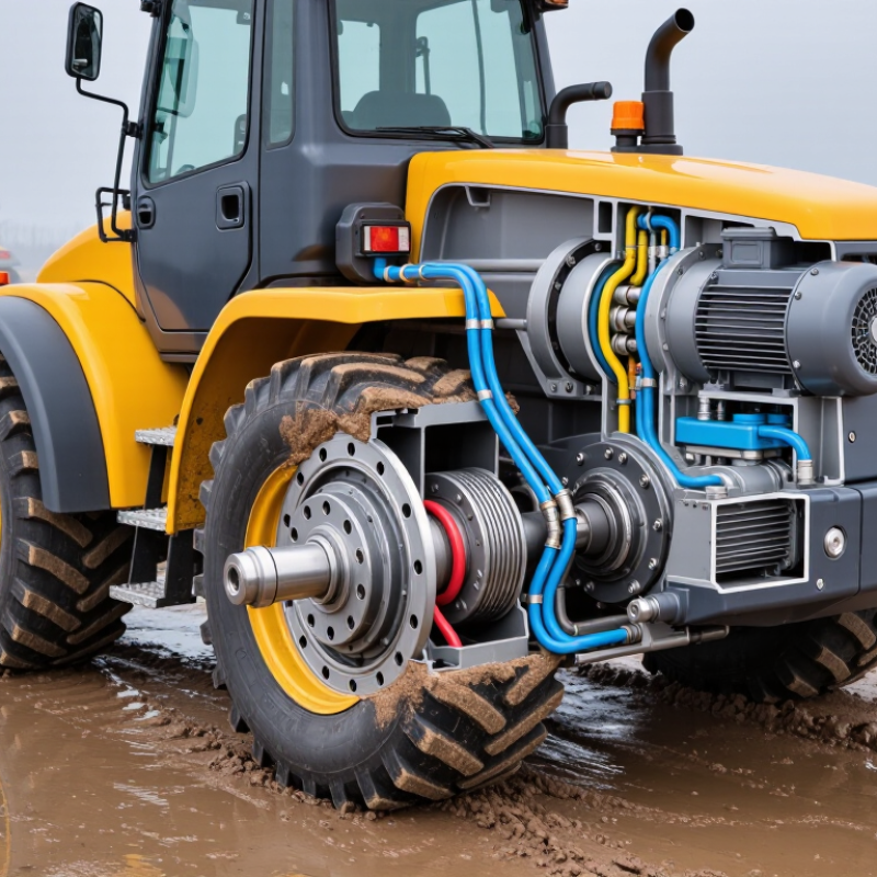
A wheel drive hydraulic motor combines a hydraulic motor, planetary gearbox, brake, bearing, and wheel hub. Pressurized oil enters the motor and creates rotary force. The gearbox reduces speed and multiplies torque at the wheel. This arrangement suits compact machines that need strong traction in limited space. Low-speed control is another advantage. Operators can adjust wheel movement by controlling oil flow and pressure. The International Energy Agency reports that motor-driven systems consume about 46% of global electricity. Hydraulic systems are not automatically more efficient, but they can deliver high torque in demanding mobile applications.
Inside the assembly, sealing elements contain oil while bearings support radial and axial loads. A spring-applied, hydraulically released brake can hold the machine during parking. Relief valves protect components when the wheel meets sudden resistance. In field inspections, heat around the housing often signals excessive pressure, poor lubrication, or insufficient cooling. Small leaks matter. They reduce performance and invite contamination. The Global Mobile Hydraulic Equipment Market reports steady demand for compact hydraulic drives, especially in construction and material-handling equipment. However, market growth does not prove every application needs hydraulics. Electric drives may provide simpler maintenance in cleaner environments.
Tips: Match displacement, pressure, speed, and axle load before selection. Check return-line back pressure. Keep oil clean. Do not judge performance from torque alone. Real traction depends on tires, ground conditions, and control settings. Test the complete wheel assembly under actual duty cycles. That step is often skipped.
The chart shows how theoretical output torque increases with motor displacement at a constant pressure of 100 bar. Torque is calculated using the ideal relationship T = Δp × Vd ÷ 2π. Actual torque is lower because of mechanical and volumetric losses.
Larger displacement provides higher torque per revolution, which is useful for low-speed, high-load wheel-drive applications.
Why Choose a Wheel Drive Hydraulic Motor?
Compare 250–450 bar Hydraulic Pressure with Electric Drive Requirements
A wheel drive hydraulic motor suits machines that need high torque in limited space. At 250–450 bar, compact components can deliver strong wheel force through a small hydraulic circuit. Pressure alone does not determine performance. Flow controls speed, while pressure difference creates torque. A useful field estimate is simple: 300 bar at 60 litres per minute provides about 30 kW of hydraulic input before losses.
Electric drives require a different support system. The motor needs suitable voltage, high current delivery, an inverter, cables, and thermal control. A battery-powered system may also need heavy energy storage for long operating periods. Electric motors can offer excellent efficiency and precise control, especially during frequent speed changes. However, heat can build inside the motor, inverter, and battery pack. Cooling is not optional.
Hydraulic systems also have weaknesses. Pumps, hoses, seals, and filters require disciplined maintenance. A small leak may reduce pressure and contaminate a work area. In practical testing, measured efficiency often differs from catalogue figures. Oil temperature, hose length, wheel load, and relief-valve settings all matter. That is easy to underestimate. A hydraulic wheel motor becomes attractive when compact torque, rugged load handling, and existing hydraulic power outweigh electrical simplicity. Designers should compare duty cycles, not just peak ratings. Real operating data may change the decision.
A wheel drive hydraulic motor delivers high torque in a compact package. That torque density matters when machines must push through mud, slopes, or uneven ground. Field engineers commonly specify 85–95% overall motor efficiency at rated pressure and speed. However, this figure is not universal. Leakage, oil temperature, valve losses, and poor alignment can reduce real output. The U.S. Department of Energy’s 2022 Industrial Motor Systems Market Assessment notes that motor-driven systems consume more than half of industrial electricity in many facilities. Small efficiency losses therefore become operating costs.
Speed range deserves equal attention. A wheel motor may offer strong starting torque, but its efficient speed window can be narrower than expected. A design rated for 1,000 revolutions per minute may perform poorly near stall. ISO 4409:2019 recommends testing displacement, flow, torque, and speed under controlled conditions. Use measured data, not only catalogue claims. I have seen systems meet torque targets while losing efficiency through oversized hoses and contaminated oil. That mistake is common.
Tips: Compare starting torque, continuous torque, and peak torque separately. Check efficiency at your actual pressure and speed. Also, leave thermal margin. A motor running at 95% efficiency on paper may still overheat in a dusty field. Test the complete circuit. The motor alone is rarely the weakest link.
A wheel drive hydraulic motor deserves attention where torque, space, and traction meet. Its planetary reduction converts high-speed hydraulic flow into strong wheel-end torque. This reduces the need for a separate gearbox. It also keeps power close to the wheel, which can simplify drivetrain packaging.
Load capacity depends on more than peak torque. Engineers should compare continuous torque, shock-load ratings, bearing capacity, and pressure limits. The U.S. Department of Energy reports that hydraulic hybrid systems can improve fuel economy by up to 35% in suitable stop-and-go applications. That figure is not universal. Poor sizing, excessive heat, or unstable pressure can quickly reduce the benefit. A real machine may face sudden impacts, uneven ground, and frequent reversing.
Wheel-end durability requires disciplined protection. ISO 4406 cleanliness levels help control particle contamination in hydraulic oil. Even small particles can damage valve surfaces and accelerate wear. Planetary gears need correct lubrication, accurate alignment, and sufficient bearing support. SAE J1176 provides useful guidance for evaluating mobile hydraulic system performance and safety. Field inspections should check seal leakage, hub temperature, unusual noise, and torque loss. Do not trust the catalog rating alone. It may describe ideal conditions, not a muddy worksite after years of service.
| Assessment Dimension | Representative Engineering Data | Why It Matters | What to Verify Before Selection |
|---|---|---|---|
| Planetary Reduction Ratio | Typically 5:1 to 50:1 per reduction stage or assembly | Planetary gearing increases output torque while allowing the hydraulic motor to operate at a practical speed. The compact coaxial layout also helps keep the wheel-end package short. | Match the ratio to vehicle speed, motor displacement, hydraulic flow, and required tractive effort. Confirm whether the stated ratio is the total ratio or only one stage. |
| Output Torque | Calculated from pressure, displacement, reduction ratio, and efficiency | Higher output torque improves starting performance, hill climbing, and the ability to overcome rolling resistance or soft ground. | Use the continuous and intermittent torque ratings separately. Check the calculation under the lowest operating pressure and highest expected load. |
| Hydraulic Motor Displacement | Common wheel-drive applications use approximately 50–1,000 cm³/rev | Larger displacement generally produces more torque per revolution but requires more oil flow for a given wheel speed. | Check displacement against available pump flow, maximum pressure, motor speed, and the required vehicle travel speed. |
| Operating Pressure | Many mobile hydraulic systems operate around 210–350 bar; application limits vary | System pressure directly influences available hydraulic torque. A suitable motor must tolerate both continuous pressure and short pressure spikes. | Compare continuous, peak, and case-pressure limits with the machine's relief-valve setting and transient load conditions. |
| Overall Mechanical Efficiency | Often approximately 85%–95% for a motor and planetary reduction assembly at rated conditions | Higher efficiency reduces heat generation and improves the amount of hydraulic power converted into useful wheel power. | Request efficiency data at the actual pressure, speed, temperature, and load rather than relying only on a nominal maximum value. |
| Continuous Load Capacity | Must be specified as a continuous output torque or wheel load rating | Continuous capacity determines whether the wheel drive can work for extended periods without excessive gear, bearing, or oil temperature rise. | Confirm the rating includes the complete wheel-end assembly and identify the permitted duty cycle, oil temperature, and cooling conditions. |
| Intermittent and Peak Load Capacity | Usually higher than continuous capacity, but limited by duration and duty cycle | Short-term reserve helps the machine start under load, climb obstacles, or handle temporary traction peaks. | Check the maximum duration, allowable frequency, and minimum time between peak-load events. Do not use intermittent ratings as continuous ratings. |
| Radial Wheel Load | Determined by bearing arrangement, tire offset, wheel diameter, and load distribution | Wheel-end bearings carry vehicle weight and external forces from the tire. Excessive radial load can shorten bearing and seal life. | Calculate static, dynamic, braking, cornering, and impact loads at the actual wheel offset. Verify the permitted radial load at the specified speed. |
| Axial Wheel Load | Application-specific; affected by side loads, slopes, and cornering forces | Axial capacity is important for machines operating on slopes or with frequent turning and side loading. | Check both thrust directions and confirm whether the rating applies to the complete hub, bearing set, and mounting arrangement. |
| Planetary Gear Load Sharing | Multiple planet gears distribute torque around the sun gear | Load sharing can provide high torque density and a compact package compared with a single large spur-gear reduction. | Review carrier stiffness, planet-bearing design, gear alignment, tooth hardness, and manufacturing tolerances. |
| Gearbox Service Life | Commonly evaluated by gear fatigue life, bearing life, and duty cycle rather than time alone | Service life depends on torque spectrum, speed, lubrication, temperature, contamination, shock loads, and maintenance quality. | Request the calculated gear and bearing life for the real load spectrum, including reversing, braking, and impact events. |
| Wheel-End Sealing | Seal design should address dust, water, mud, and pressure fluctuations | Effective sealing protects bearings and planetary gears from abrasive contamination and prevents lubricant loss. | Check seal material, shaft surface finish, contamination resistance, allowable pressure, and suitability for washdown or submerged conditions. |
| Lubrication Requirement | Gearbox oil type, quantity, viscosity, and change interval are design-dependent | Correct lubrication controls gear wear, bearing temperature, friction, and corrosion. | Verify oil grade, fill level, installation orientation, breather arrangement, inspection interval, and compatibility with operating temperature. |
| Wheel Speed Capability | Calculated from hydraulic flow, motor displacement, and reduction ratio | The correct speed range provides controllable travel without overspeeding the motor, bearings, or planetary gears. | Check continuous and maximum speed at minimum and maximum flow. Include overspeed conditions caused by towing or downhill travel. |
| Braking and Holding Function | May require a spring-applied, hydraulically released parking brake | A dedicated brake can hold the machine when hydraulic flow is unavailable and improve parking safety on slopes. | Confirm static holding torque, dynamic braking capacity, release pressure, fail-safe behavior, and compatibility with the vehicle control system. |
| Thermal Capacity | Limited by hydraulic losses, gear losses, ambient temperature, and cooling airflow | Excessive heat reduces lubricant life, accelerates seal aging, and can lower motor efficiency. | Evaluate continuous duty at the highest ambient temperature. Confirm allowable housing, oil, and case-drain temperatures. |
| Contamination Tolerance | Hydraulic cleanliness is commonly managed using an ISO 4406 cleanliness target specified by the system designer | Particles can damage motor valves, bearings, gear surfaces, and seals, reducing efficiency and service life. | Specify filtration, flushing procedures, breather protection, and the required cleanliness level for the complete hydraulic circuit. |
| Installation and Maintenance | Coaxial wheel-end packaging can reduce drivetrain components and connection points | Fewer exposed mechanical components may simplify installation and reduce maintenance compared with a separate motor, gearbox, axle, and chain arrangement. | Check mounting stiffness, hose routing, wheel-bolt pattern, access to inspection points, drain-port position, and replacement procedures. |
| Selection Decision | Choose when compact high torque, independent wheel control, and hydraulic integration are priorities | A wheel drive hydraulic motor is particularly suitable for low-speed, high-torque mobile equipment requiring flexible layout and controllable traction. | Approve the design only after checking torque, speed, pressure, flow, wheel loads, braking, thermal limits, sealing, lubrication, and the complete duty cycle. |
A wheel drive hydraulic motor should match the machine’s real working conditions, not just its catalog rating. Start with displacement. Larger displacement usually produces more torque per shaft revolution, while smaller displacement supports higher speed. This choice affects climbing ability, control, and heat generation.
Flow rate determines motor speed. Estimate the pump’s usable flow, then compare it with the motor’s displacement and efficiency. A simple calculation can look perfect on paper. Field results may differ because hoses, valves, oil temperature, and internal leakage reduce available flow. Leave practical margin.
Torque matters most when the machine starts, climbs, or carries uneven loads. Check continuous and peak torque separately. A motor may survive a short overload but wear quickly under repeated shock loads. During testing, observe wheel speed, casing temperature, and pressure changes. Small details matter.
Duty cycle is often overlooked. Intermittent work allows cooling periods, while continuous operation demands stronger thermal management. Mud, slopes, and frequent reversing can create harsher conditions than expected. Choose based on the hardest normal shift, not an ideal test. Recheck the selection after installation. It may need adjustment.
It combines a hydraulic motor, planetary gearbox, brake, bearing, and wheel hub. Pressurized oil creates wheel rotation.
They provide strong torque in compact spaces. This helps machines climb slopes, cross mud, and handle uneven ground.
The gearbox reduces motor speed and increases wheel torque. This supports traction during starting and heavy pushing.
Larger displacement usually provides more torque per revolution. Smaller displacement generally supports higher wheel speed.
Hydraulic flow determines motor speed. Hoses, valves, temperature, and internal leakage can reduce the expected flow.
Compare starting, continuous, and peak torque separately. A motor may tolerate short overloads but suffer under repeated shocks.
Not completely. Leakage, heat, valve losses, contamination, and alignment can lower real efficiency.
Heat around the housing may indicate excessive pressure, poor lubrication, or weak cooling. Small leaks also reduce performance.
A spring-applied, hydraulically released brake can hold the machine when parked. It should be checked during routine inspections.
Test the complete wheel assembly under actual duty cycles. Check speed, pressure, temperature, traction, and reversing loads. Catalog data is not enough.
A Wheel Drive Hydraulic Motor converts pressurized hydraulic fluid into rotary motion directly at the wheel, combining a hydraulic motor with a planetary reduction system. Its compact structure provides high torque density, reliable traction, and controlled wheel movement in demanding mobile equipment. Operating pressures of approximately 250–450 bar can deliver substantial power in a smaller package than many electric drive systems, while hydraulic flow determines motor speed and displacement influences torque and operating range. In practical applications, efficiency may reach about 85–95%, depending on load, pressure, temperature, and system design.
The planetary reduction stage increases output torque, supports heavy loads, and helps protect the wheel end under shock conditions. When selecting a motor, engineers should match displacement, required flow rate, available pressure, output torque, speed range, and duty cycle. They should also consider heat management, bearing capacity, sealing performance, maintenance access, and expected terrain. A properly sized Wheel Drive Hydraulic Motor can provide durable, responsive, and efficient power transmission for equipment requiring strong low-speed performance and dependable wheel-end operation.

Weitai Hydraulic